Getting started
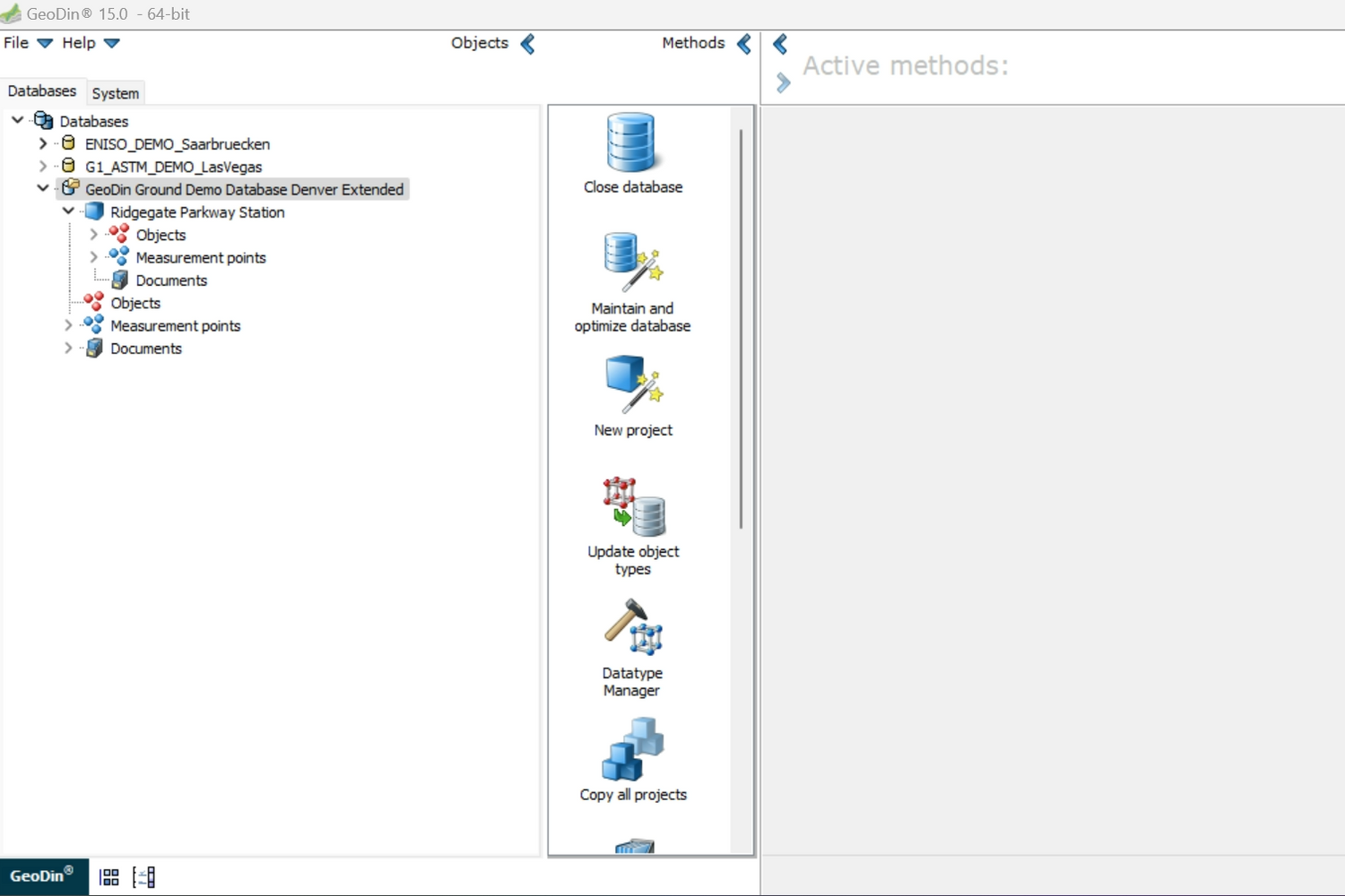
1. Open GeoDin
Load the project data you’re working/the team is working on.
This step ensures that the factual data matches the visual data that will later be viewed in Civil 3D.

2. Verify borehole information
Navigate to Objects > All Objects to view the detailed
borehole information.
Here you can find information such as: location name, project title, report number, client, method, purpose, area, city, and country.
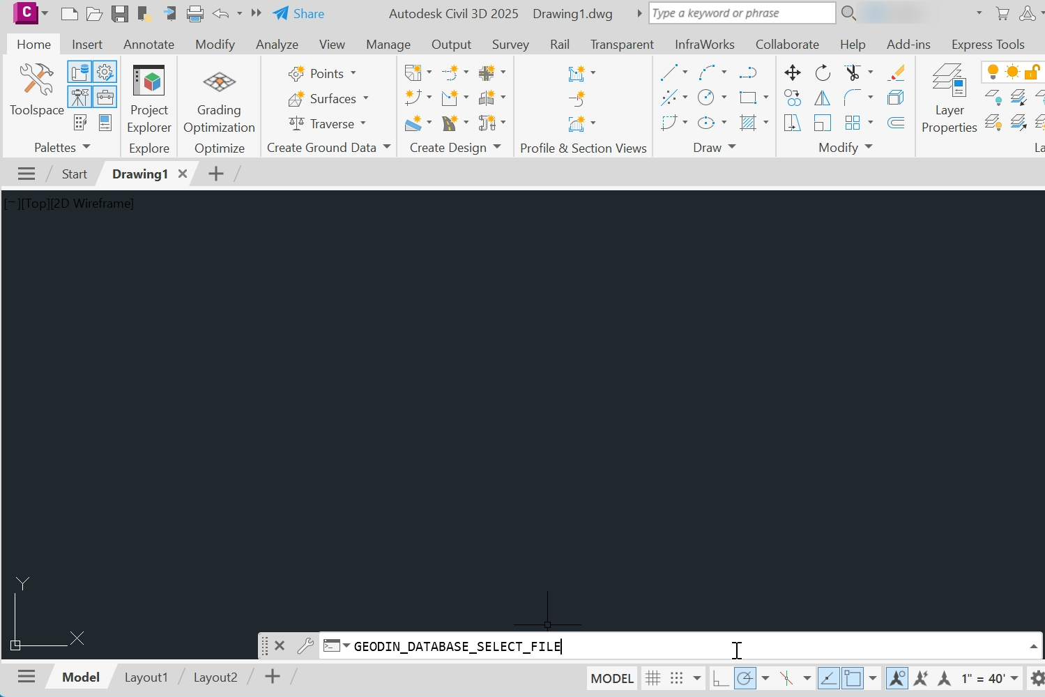
3.Open Civil 3D
Ready to visualise your ground data? Launch Civil 3D.
The GeoDin Ground plugin can be activated by typing commands in Civil 3D. Commands tell Civil 3D to perform specific actions such as drawing locations or surfaces.
Enter the command GEODIN_DATABASE_SELECT FILE.
This will prompt you to select the database you
want to work with.
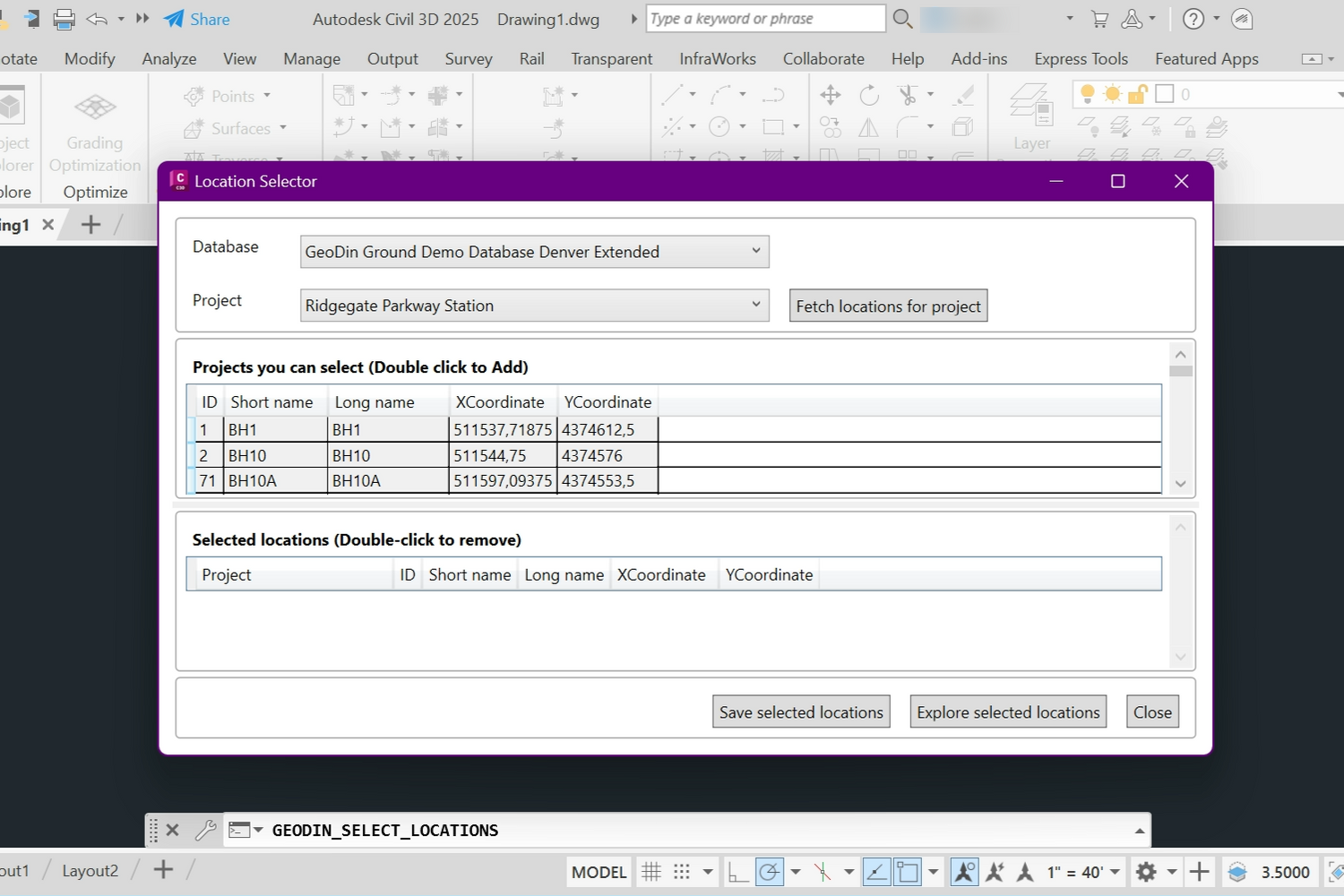
4.Select locations
Enter the command GEODIN_SELECT_LOCATIONS. The database and related project will be displayed. Once you choose the correct project, click "Fetch locations for project" to load borehole coordinates. Select all locations using CTRL+A and click "Save selected locations".
Visualizing geological data using different commands
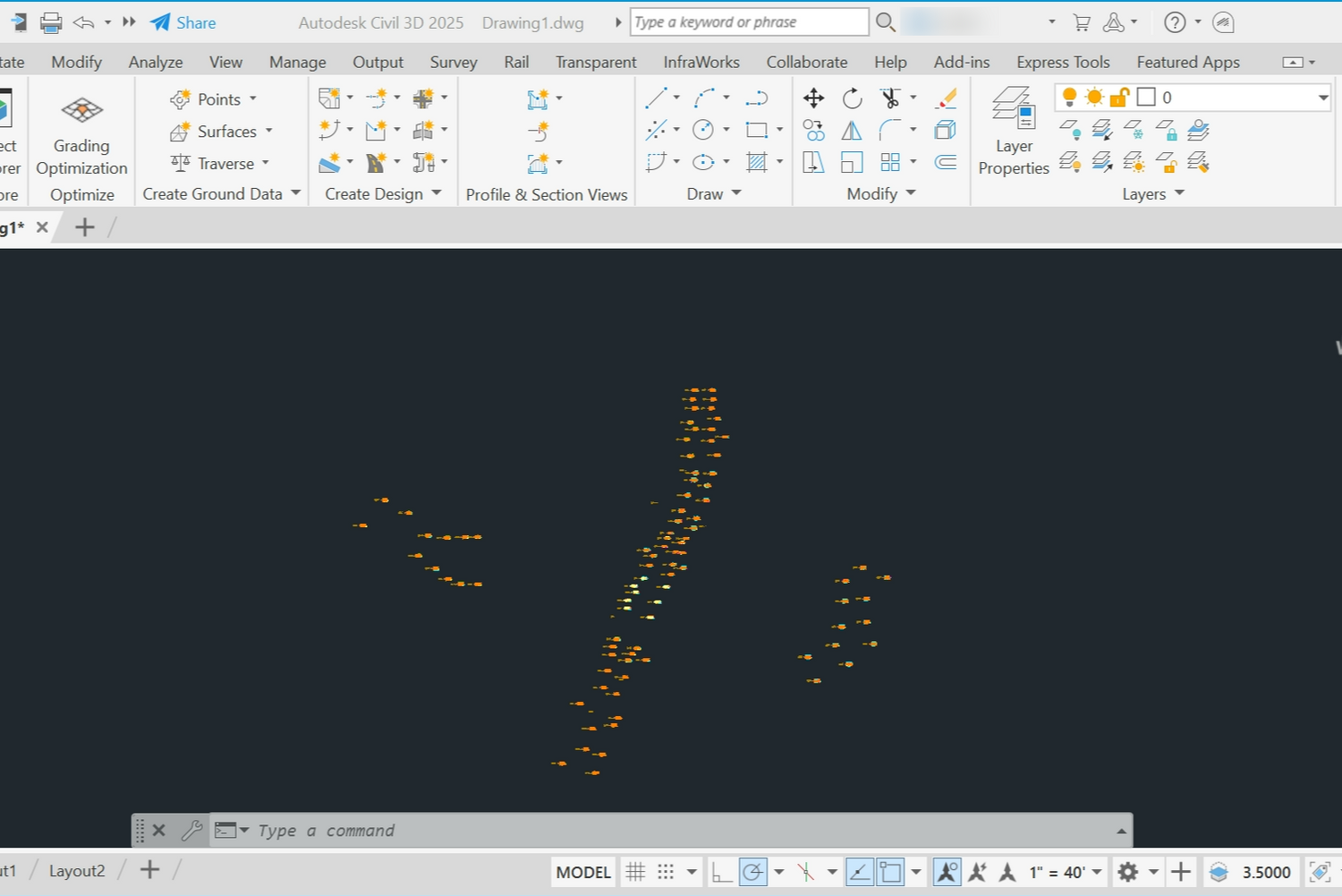
1. Draw boreholes
In order to visualise the boreholes enter in the command tab GEODIN_DRAW_BOREHOLES
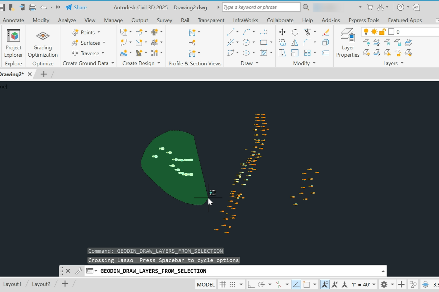
2. Draw selected layers
In order to look at a specific group of boreholes and
visualize them independently of other groups, use the command, use the command GEODIN_DRAW_LAYERS_FROM_SELECTION.
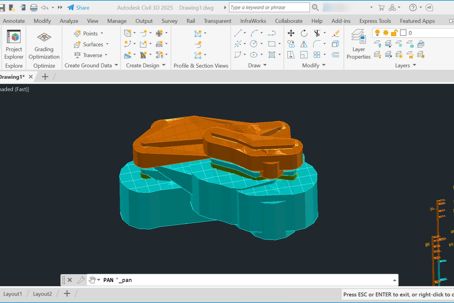
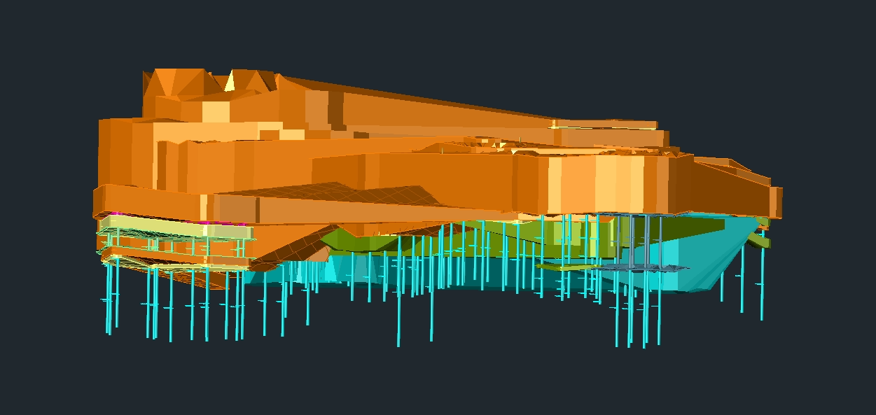
3. Draw surfaces with lithology
Employ the command GEODIN_DRAW_LAYERS to create 3D surfaces based on the lithological data. This command calculates the surfaces between all the boreholes and creates a surface.
This command helps you to visualize specific borehole locations with lithology, represented by different colours which correspond to the different types of layers in the ground (e.g., clay, sand, stone).